As it was signalled before, pH meter is nothing else, but precise voltmeter, that measures EMF of the pH electrode. However, most commercially available voltmeters will be of no use. pH electrode has internal resistance in the range of 10-100 MΩ. To reliably measure potential voltmeter must have internal resistance at least 100 times larger, while most digital meters available have resistance in the range of 1-10 MΩ, thus they are unsuitable.
Making high-resistance voltmeter is not easy, as such devices are much more sensitive to temperature changes and electromagnetic noise, as well as to electrostatic charges. However, with electronic elements available today it is not very difficult to create an amplifier of very high gain and very high input resistance. Such amplifier can be used as interface between pH electrode and voltmeter (see example circuit diagram below) - and that's how many of the shelf pH meters work.
While the basic ideas behind the pH meter working didn't change much since 1934 (see pH meter history), reliability and precision of todays pH meter are much better, although they are still limited by the electrode construction and properties of the solution itself. As every other lab device todays pH meter is digitized and able to communicate with computer, some models can automatically record data for extended period of time and print the results and so on.
There are two groups of pH meters - bench and portable. Bench pH meter is usually more precise and has more options built in - most often it can be used in any potentiometric application. Portable devices are much simpler, typically able to measure pH only and less accurate. However, in the field work they can be invaluable.
Below is example circuit diagram of the pH meter. Note that device is built using several resistors and switches, the only active element being carefuly selected operational amplifier. Switches and resistors are necessary to select the mode of operation (pH meter or milivoltmeter for potentiometric applications) and to allow calibration.
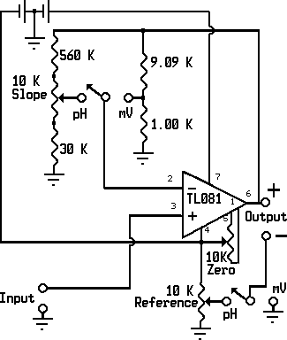
The meter is a dual mode non-inverting amplifier. A DPDT switch is used to select between milivolt mode (gain=10V/V, reference=0V) and pH mode (adjustable gain and reference). A 10K ohm trimmer potentiometer is used for zero adjustment (offset null).
1. Input section - the cell is connected to the non inverting input of a TL081 JFET input operational amplifier through a shorting type 2.5 mm plug (not shown in the schematic diagram). When the cell is not connected, the 2.5mm plug shorts the input to ground, this permits adjusting zero in milivolt mode, and reference in pH mode.
2. Amplifier section - a TL081 operational amplifier is connected as a non-inverting amplifier, with the feedback resistor network selected by one pole of a DPDT switch.
In milivolt mode, the network consists of a 9.09K ohm resistor in the feedback loop (R1), and a 1.00 K ohm resistor to ground (R2). The gain is given by:
Gain= 1 + R1/R2 = 1 + 9.09K/1.00K = 10.09 = ~10
In pH mode, the network consists of a 560K ohm resistor (R3), a 10 K ohm linear taper potentiometer (R4), and a 30 K ohm resistor to ground (R5). The variable terminal of the potentiometer is connected to the inverting input of the op-amp and the gain is given by the equation that follows, where P is the position of the potentiometer's wiper with respect to the 560 K resistor, it varies between 0 (all the way counter clockwise) and 1 (all the way clockwise):
Gain = 1 + (R3+P x R4)/(R5+(1-P) x R4)
At the lowest point (P=0):
Gain=1 + 560K/(30K + 10K)= 1+560K/40K = 15
At the highest point (P=1):
Gain=1 + (560K+10K)/30K= 1+570K/30K = 20
The gain required at 25°C, for 1 Volt per pH unit is about 16.7, the circuit allows for adjusting between 90% and 120% approximately.
3. Output section - the output is taken from the output of the TL081 directly and can be read with any DC voltmeter. In milivolt mode the reference is 0. The voltage reading is 10 times the cell voltage, permitting 0.1 milivolt resolution with low cost voltmeters. In pH mode the reference can be adjusted from pH 0 to pH 12 through a 10K ohm linear taper potentiometer, for use with Carbon/Quinhydrone electrodes. With the reference properly adjusted, the output in volts will be the actual pH of the indicator solution. With low cost voltmeters the accuracy is about 0.05 pH units when properly calibrated.
Curcuit diagram and description used with permission and slightly modified (power supply replaced with battery, for the sake of clarity). Original version was published on The Low Cost Equipment Project at UNESCO/IUPAC site (original link no longer working).